Nathan’s DHW Project
DHW Project
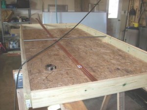
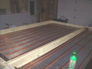
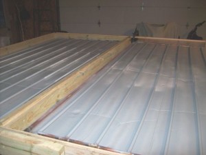
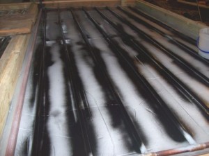
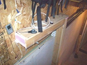
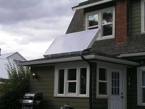
Here is a recently completed, very nicely designed, customer DHW project. Nathan has adjustable legs on the back of the collector, allowing for different angles on the unit, based on the seasons and sun angle. He also designed his own controller, with nice details about that system available on his site as well. Click here for more details; diysolar.nateful.com
Knick’s Solar Collector Assembly
>>>>> click here to view slideshow with descriptions <<<<<
Joe’s DHW System
Getting an impressive 3-year Return on a $1,000 System
9/23/10 Update;
Joe bypassed his hot water heater, turned the breaker off for most of 7 weeks, and ran all but two days of that period without “grid powered” hot water.
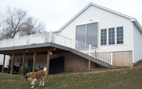
He’s been very happy with the 30 plus dollar a month drop in his electric bill, and decided to try turning off and bypassing his electric water heater. We live in the U.P. of Michigan, so we’re not in the greatest sun belt area of the U.S. He shut off and bypassed the water heater for all but two days of that 7 week period. He has recently turned the electric water heater back on, since we’ve been a bit marginal on sunshine the last couple weeks. This does show how efficient these home built solar collectors are.
Sometimes working with a nut (me) can be infectious, as my brother Joe found out. He started playing with a pop can collector at the same time I did, about 3 years ago. His pop can collector was much more involved, and produced an impressive amount of heat when placed inside the patio door on the south side of his home. Joe still uses that collector today.
Seeing my multiple “test panels” and my work on our large home array, he decided to build a 2-panel array for his domestic hot water. Most of the design came from ideas on Gary’s www.builditsolar.com web site, specifically Gary’s $1,000 DHW system he shares with great detail. Joe used our stamped absorber, electing to go with the standard 70% wrap.
The Collector
The collector is two standard 4′ x 8′ panels, built separately, but with the provision to mate them once installed on his house. The design replicates mine with 2 x 6 outside frame material. He cut a recess in the back of the frame so his backing board would sit flush with the back of the frame. Joe used ½” OSB for his backing board (I used ¾”, but mine are “self supporting” outside, not placed against the side of the house). He installed ½” Polyisocyanurate (Styrofoam with the aluminum facing) inside the panel. This is a design we like for several reasons. The absorber is touching the insulation, not the backing board, which allows maximum efficiency of the absorber to go to the tubing. We loose no heat to the backing board. The other advantage is the insulation is not exposed at the back of the panel, where it can be damaged during the construction or when erected on site.
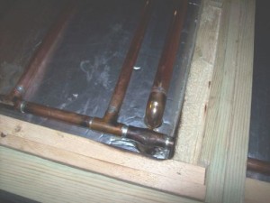 Joe used ½ copper for both his manifolds and his risers. This has proven to NOT be an issue (same size manifolds as the risers) in a 2-panel system. There’s not enough total flow area that the restrictive manifold size is an issue. I would advise larger manifolds on systems exceeding 3 panels. Going with ½” throughout saved considerably on the “T” fittings, allowing him to use standard solder fittings. Joe laid out the copper tubing grid on a bit less than 6″ centers to allow for 8 risers per panel. The manifolds are “pitched” about ¼’ for drain-back, with the highest point on each panel opposite the “low point” entry. He designed the inlet as a “T” on the right bottom corner of the left panel, and had a union exiting the panel to the right to connect to the low point manifold on the right panel.
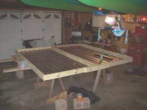 The top “returns”, once hitting a high point on the outside corners of each panel, pitched downward and back to the center of the two panels. They “T”ed at the center, inside the panel, and one 3/4” copper return drops down to exit the array adjacent to the supply. Running the returns “inside” the panels keeps the circulating water warm before exiting the array. This design also makes the plumbing easier, as both the supply and return run next to each other. This allows insulating them in the same “chase”, but separating the pipes with insulation as well so we don’t lose heat between the return and the supply line.”
Joe primed and painted both the tubing and the inside groove of the absorber. This is to avoid dissimilar metal corrosion, which will happen between copper and aluminum if left to contact in their bare state. He used the modified Vice Grip clamps when installing the absorber to ensure good contact between the absorber and the tubing. Since we screw through the insulation before contacting wood, the length of the screw needs to be exact for the depth of the insulation and backing board. In this case, 1″ drywall screws were the perfect length. Once the aluminum absorber was secured over the copper tubing, the panels were turned over and a small grinder was used to knock down any protrusion of the screws. Any protrusion would be a “cut waiting to happen’ when handling the panels later.
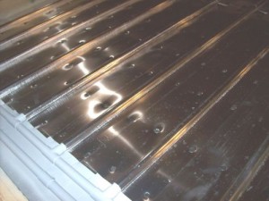 Joe elected to clean the absorbers good with soap and water before installing them, and then a simple “wipe down” with a damp rag was done before priming and painting. For my large array, I used a PPG process, with a PPG cleaner and then wiped with their aluminum prep. Since I’ve had problems with corrosion after the fact (my brazed joints reacted with the aluminum prep), I’m thinking Joe’s method on a glazed panel is probably sufficient, and certainly avoids the problems I had.
Mounting the collectors;
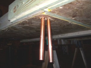
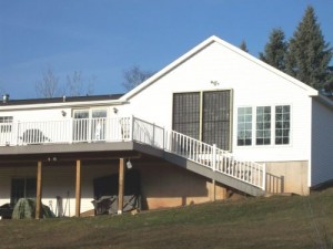
Since the collectors were “panelized”, they were not too difficult to install. Joe cut his siding out to the exact dimensions of the two collectors so they are mounted directly on the wall sheeting, not the siding. The panels had the supply and return lines protruding out the back before being mounted on the wall, so the holes for those lines had to be drilled before mounting the panels. He installed flashing at the top, running it under the siding and over the top of the collector to avoid water penetration under the siding at this joint. Connections for the two panels were “fitted” with the collectors lying on saw horses in the garage, so final assembly was a snap. Soldering those connections required a little different approach to avoid melting the Polyiso under the tubing. He laid some small pieces of aluminum scrap under the solder joint, and then squeezed in a wet rag between the aluminum scrap and the solder joint. A pretty aggressive torch must be used at this point; one that can get a lot of heat in there quick. Otherwise the wet rag will sap the heat away from the joint faster than the torch can melt the solder. I’ve found forcing a putty knife under the joint allows a bit of room to work with. The absorber screws could be loosened a bit too if needed.
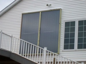 His final step was to install the twin wall glazing. He tested the fit in the shop, but didn’t install the glazing until the panels were installed on the house and plumbed. The panels were actually pressured with water to test for leaks before closing them up. A groove had been cut in the 2 x 6 framing during the initial frame work to recess the glazing. There was a bit of extra room cut in for glazing expansion too. Notches were installed in the frame work during the original assembly for the galvanized ½” conduit glazing supports. Joe only installed one support, at the 4′ point of the panel. I’ve used 2 supports over the 8 feet on my panels, but not sure that’s actually been necessary.
The Tank
Joe found an unusual tank location; one that utilized completely wasted space and actually had some unique features that worked in his favor. The steps to his basement are in a breezeway between his home and his garage. This is an unheated area, but the steps are between the poured walls of his basement and the poured foundation of the garage. The 4′ wide area of the steps was ideal for placing the tank under the steps, in the wasted and unused area. The job required pulling up the steps during the construction, but 3 sides of his tank were already formed and quite sturdy. He only needed to install one wall to the tank, the wall facing the steps. To get sufficient tank space, he modified the top part of the tank, pitching it at the same angle as the steps for clearance. After installing 3″ of Polyiso on all sides, he capped the top and left a “man hole” type opening for access.
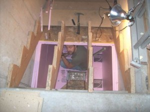 Joe used “pool liner” like Gary Reysa does with all his homebuilt tanks. This phase of the project almost became fatal, in the most unusual way. Joe placed the pool liner in the tank, and then crawled into the tank to “fit it” to the tank walls. This requires lots of folding and fitting so the liner will not tear once stressed when filling with water. During this stage, the excess liner lying outside the tank fell over the access hole. Joe did not initially get concerned, he had sufficient light to work, but soon he noticed it was getting hard to breathe. He was running out of oxygen. He attempted to move the liner off the top hole, but it was heavy and finding the opening was nearly impossible. At a point he was about ready to “cut his way out” with his razor knife, he finally found a crease that led to the opening in the liner. A helper at this point would have been a real benefit.
Plumbing, Exchanger & Controls
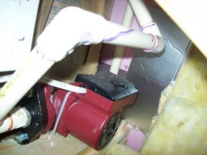
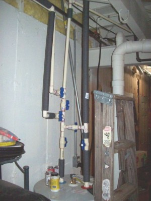
Joe installed a 300′ coil of ¾” PEX for his heat exchanger. His final tank size is 225 gallons, so his capability to store heat several days without sun is very good. For his circulation pump, he picked a Grundfos pump with three speed settings, allowing him to find the most efficient flow rate for his system. His pump is located just outside the tank, insulated to the tank for freeze protection. He has a small incandescent light on a timer he uses only when the outside temps get extremely cold. His plumbing from the collectors to the tank is CPVC, running at a steady pitch downward (for drain-back) and is well insulated. The plumbing for the DHW is simply routing the supply side of his water heater through the heat exchanger in the solar water tank before it arrives to his electric water heater. Again, all plumbing in this loop is well insulated. Joe installed several valves in his system to allow bypass loops as desired. He can bypass the solar tank, or he can bypass the electric water heater.
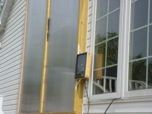 Wanting to keep his cost down, Joe did not want to purchase an expensive controller like the GL-30 I purchased. We’ve had success with the “button” or “snap” switches in our test panels, and on the pool array. We installed these switches on the absorber, as far away from the tubing as possible, but inside the collector. I suspected it was possible if the water temp in his tank exceeded the 120 degree mark (he used a 120 degree snap switch), the heat from the water would keep the absorber warm enough to “fool” the switch that the sun was still shining. Well, the theory was correct. Even installing a variable temp switch where he could keep tweaking the temp setting, the warm water would “fool” the control and the pump would continue to run, actually dropping the tank temps. Once he got his tank water temp up, he had to manually shut the pump down. We devised a separate “box” with a small piece of aluminum absorber placed over insulation. The box is the size of an 8 x 10 picture (he actually used the glass from an old picture frame). He installed a small “hand access” door on the side so he could adjust the temp switch as he experimented with it. Now the water flow had no bearing on the temperature of the “flat black” aluminum, only the sun could impact the operation of the switch. He installed a couple small holes at the top and bottom to allow for more responsive temperature change. Even with this control system, it wasn’t quite right. The system would not turn on soon enough, and it was running too late in the day. The next modification was to mount the box on a swivel, allowing Joe to orient the box more easterly to get the control to match the solar energy we wanted. This final modification has worked flawlessly. Joe now has a control that works much like the expensive $150 – $200 controllers, and has about $35 into it (and a bit of sweat).
Going Live & Results
Joe’s system went live December 2009. Unlike my system, with wood stove back-up, his system relies solely on the sun. The water he filled the system with, coming from the local city line running under the street was about 45 degrees (got to love living in the U.P. of Michigan). It took several days of solar exposure to get the tank temp up to 75-80 degrees. Then a couple good days of sun later in December popped his tank temp above 100 degrees. Keeping in mind the toils he had for the first several months developing a good pump control system, the results were still impressive. After two months of good operation, he was able to see a $30 drop in his electric bill, clearly from the minimum use of his original water heater. The system has been live for 5 months, trouble free, and his trend on the electrical usage is still in the range of $30 a month.
Click here to download “Domestic Hot Water System” cost chart (in Adobe Acrobat)
Click here to download “Domestic Hot Water System” utility bills chart (in Adobe Acrobat)
The “Savings @ Equal Rate” figures are computed based on two electrical rate increases over the last year. Electrical usage equal to last year at the new “higher” electrical rate would have placed his bills at that amount more.
October 1, 2010 update;
Joe saw a slight increase in his electrical usage this summer, all due to a tremendous amount of laundry his wife, Brenda, was doing because of a new litter of St Bernard puppies they had in residence. The pups are now gone and he experienced his lowest KWH month (this September) since owning his house. The modest home has averaged 700 to 1,000 KWH’s a month before the solar hot water system was installed, mostly this low due to his work with a Kill-a-watt meter a few years ago, and the related changes from that valuable information. This past month his usage was 512 KWH’s. Ironically, his cost for the 516 KWH’s in September of 2010 was less than a $1 lower than his bill from October of 2008, when he used 891 KWH’s. His electrical rate in 2008 was 9.3 cents per KWH, and now is 16.1 cents per KWH. Seems like we are at a good time to consider energy use reduction and renewable energy options!!
