Simple pop can hot air collector
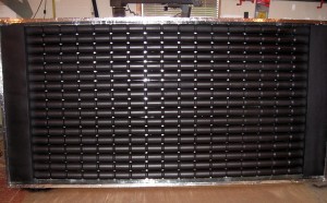
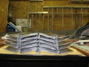
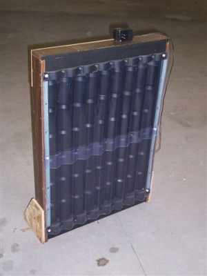 Pop can collectors are a popular “first project” for people interested in solar energy, but not sure about the value or efficiency of solar to make heat. This is the first solar project I did, a pop can solar collector. It consists of a box large enough to hold 6 pop cans vertically, and 9 horizontally. The pop cans were drilled with a 1″ hole saw at the top and bottom, cleaned and painted flat black, and then stacked inside the box on top of each other. I used no sealant between the cans, but many builders do.
Th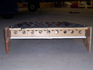 e bottom board of the collector was drilled with a 1 1/4″ hole saw, at locations to match each individual stack of cans inside the collector.
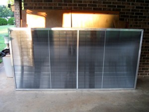
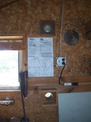
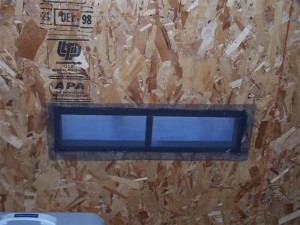
I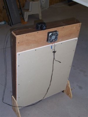 used a scrap piece of poly carbonate to close out the front, and a scrap piece of drywall to close the back. I found an old computer that was trashed and removed the “muffin fan” from it. The fan was located at the top of the panel, on the back side and centered. I used an old DC inverter to run the fan when the sun was shining. The unit was placed in my living room, in front of a large window facing south. It was a great project to take on, as it was quick to build, worked impressively, and I had little money in it. This unit now sits in the window of my hangar, with the fan power plugged into the “fan side” of my large hot air solar collector. It only runs when the big panel is making heat.
******************************
Joe’s large pop can collector
This is a great project for someone interested in solar, but not quite ready to spend the money and time to build a more complicated system. Having provided solar presentations at several schools over the past few years, I’ve seen interest from teachers to take on small projects like this for their science classes. Hopefully the information provided is enough to get you started.
>>>>> click here to view slideshow with descriptions <<<<<
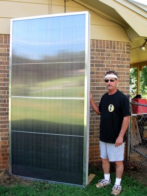
This was Joe’s first experiment with solar. Initially he used it in his “part time heated” garage. After seeing fairly impressive heat coming out of this 2′ x 5 1/2′ collector, He decided he wanted to use the collector in his home. Joe inverted the box, relocated the lower manifold to the bottom again, removed the top board, and installed an old computer muffin fan to extract the heat. A snap switch was purchased from Mark at Controls Supply (see Tips & Tricks for his contact info). The collector was placed in front of a south facing patio door. This is a hallway with an open ceiling to his living room. Having a set-back thermostat, his house temp is set for 62 degrees from 8 AM to 4 PM during the winter. Joe found that once he placed the pop can collector in his home, on sunny winter days, his 1300 square foot home would be at 65 degrees when he came home at 3:30 PM. It was evident the collector was adding enough heat to keep the furnace from running, at least when the sun was shining anyway. A house designed for better passive solar clearly sees the same thing without a collector, but his home is a poor design for capturing solar energy (one south facing window). Joe is building a new pop can collector, larger and of better quality. See his comments below.
“Crude but it’s my test panel which got good results. I cut better holes in the new cans and will work harder on fit & finish. 🙂
Turns on with button switch but has to use a timer to turn it off since the house temp will fool the switch”.
******************************
Rick Louys’s Solar Box
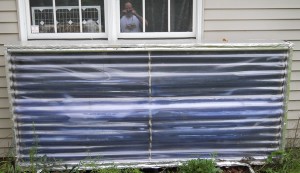 A friend of mine, Tom Sullivan, built a solar hot air collector on the wall of his aircraft hangar. He was getting good results from his project, so I started researching solar heat. I had been under the misconception that it would not be feasible in the Upper Peninsula of Michigan.
Extensive research online at builditsolar.com and Mother Earth News indicated that solar heating works up North as well as down South. After checking out a lot of designs and figuring out the best place to do a test project on my house, I built a removable window solar box collector. I figured if this were successful, I could build large scale collectors on the South sides of my house and my detached workshop. The info on the web said that a person can reduce heating costs a fair bit by utilizing solar power. I was pretty skeptical until I saw the results.
The project took me two weekends working off and on with pretty frequent breaks to build, and cost me about $120 in materials for the box itself. A solar panel, an attic thermostat, and dc fans raised the total materials cost to approximately $300.00. I put about 30 hours into the construction of the box. This was a time consuming project because it was customized to the location, built on the fly with modifications and additions, and built extremely tightly, utilizing a large quantity of calking. A second box would go a lot faster now with one under my belt.
I have a library room attached to my house that is approximately 14X14 feet with 8 foot ceilings. The room usually is about 2 degrees F cooler than the rest of the house, so I decided to try installing a solar air heater window box there to see what it would do.
I built the window box based on the Mother’s Solar Heat Grabber design found at
www.motherearthnews.com/Green-Homes/1977-09-01/Mothers-Heat-Grabber My box is built out of double layers of 1 inch thick Thermax aluminum-faced foil sheeting for a good insulation value and double layers of clear PVC roofing to act as glazing.
The box I built has a collector area of 41 inches high by 94 inches wide. The box has an internal depth of 6 inches. The box is divided in half by a Thermax sheet which divides the back cold air plenum and the front plenum, which is painted black and serves as the collector plate. All interior surfaces visible through the glazing were painted black to maximize heat generation and for aesthetic purposes. The area of the collector (L x W) is approximately 32 square feet. The volume of the collector is approximately 6.7 cubic feet (the collection area is only 2.5 inches deep, after all).
The Thermax was purchased at cost from a local hardware store which had bought it in large quantities for a commercial customer, who stopped using the material in their production process. Clear PVC roofing material was purchased at Home Depot.
I first tried using a razor knife and a straight edge to cut the Thermax, but found it difficult to make good clean cuts. I am sure it would have gotten better with more practice, but I decided to make life easier on myself and started using my table saw and my sliding mitre saw to cut the Thermax.
I assembled the box by gluing the cut pieces of Thermax together using liquid adhesive to make all parts of the box 2 inches thick for an insulation value of R-13. I caulked all joints that could communicate with the outside to maximize the tightness of the construction. I figured that the sun would not be out more than it would be, so I wanted to make sure that when the box was not generating heat, it would not cause excessive heat loss through the glazing.
I wanted a double layer of glazing to provide better insulation and reduce heat loss, so I decided to double up on the PVC roofing material.
Since I had two separate boards glued together making up the box, I made sure the inner board was shorter than the outer board, providing an inset for the glazing material so the glazing would be flush with the outside of the box. This provided a better aesthetic look as well as reduced
I glued plastic wiggle strips painted black (using Krylon paint for plastic) along each side of the box. I glued the first layer of PVC glazing (which required two sheets of the PVC roofing material) to the wiggle strips. I used silicone caulking to seal between the overlapping PVC sheets, and also used caulking to seal the gap between the edge of the glazing and the box
edges.
I then took one-sided adhesive foam weather stripping and ran it along both side edges and down the middle of the first layer of PVC glazing. Now that the weather stripping was in place on the first layer of glazing, I ran glue on the exposed side of the weather stripping, and overlaid another layer of clear PVC glazing, to make a double layer of glazing to minimize heat loss through the box. I then caulked the second layer of glazing to the box. I did not know if the adhesive would bond well with the foam weather stripping, but it ended up bonding extremely well.
I taped all joints and exposed foam using aluminum foil tape. This improved the aesthetics and helped further seal the box.
 I designed the ducts so that the collector would draw room air through one window and exhaust the heated air out the window next to it. Weather stripping around the ducts help seal the gaps when the windows are closed down onto the ducts. I was unsure what kind of results I would get due to the fact that the ducts ended up offset on one side of the long box. To be honest, I really wasn’t expecting much from the design, considering the way I modified it.
We have had a few sunny days since I installed it, but on those days, it has been fairly impressive. I measured the temperature of the collector by using a digital meat thermometer. Starting at 10 am, the box warmed up 97 degrees F and started gently exhausting air. By 11 am, it was putting out 129 degree air. By noon, it was putting out 139 degree air. The output temps dropped back down to 119 degrees by 2:00 and held there until the sun couldn’t shine on the box anymore at about 4:00 pm.
The outside temperatures were extremely cold, ranging from -10 degrees F up to 9 degrees F on those days! The box didn’t care-it just put out heat as long as the sun was shining.
The temperature in that 14×14 room, normally at 66 degrees as opposed to the average 68 degrees of the rest of the downstairs portion of the house, rose to 74 degrees.
I had found in reading that a larger volume of 90 degree air would be better than a smaller amount of 130 degree air, so I decided to add a fan. I decided for maximum benefit, I would use solar to power the fan so there would be no power costs incurred to generate the heat.
I purchased a 20 watt solar panel (to be used in future larger projects) from ebay for $145, and wired it to a small, 12 volt, 33 cfm dc computer fan to draw the air out of the collector. An attic thermostat in the circuit made sure the fan would only run when the box was producing heat. I figured the 33 cfm fan would move a lot more air than the collector would produce. Remember that the box only has a cubic area of 6.7 cubic feet, so 33 cfm should exhaust the air much faster than the box can generate it, right?
WRONG!!
The next sunny day, the collector started warming and the fan kicked on. Despite the 33 cfm fan operating, the temperature continued to rise in the collector and held at 139 degrees.
I swapped out the fan for a larger, 85 cfm dc fan. This dropped the temperature in the box to 119 degrees. The room heated up to 78 degrees, a 12 degree rise from normal!
I added another 85 cfm fan to the exhaust duct. This dropped the temperature in the collector to 97 degrees, which was maintained steadily. The temperature in the room climbed to 86 degrees!! bviously I don’t want that room at such a high temperature, but I had been leaving the door closed to measure the productivity of the solar box. The door will be left open, allowing the warm air to disperse into the rest of the house.
 I have used this heater for the past 3 years now, and the results have been consistent. This project isn’t going to totally replace my heat by any means, but I know that the heat coming in isn’t costing me a dime and is offsetting my heating costs. I haven’t tried to sit down and figure out the
BTU production, but at $2.75 per gallon current LP pricing, the investment of $300 in materials and 30 hours of time is going to have a good payback. 10 years from now, I can only imagine how much the LP saved will be worth.
******************************
Another hot air collector
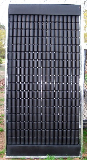
Here is one of the nicest pop can collectors I’ve ever seen. Greg from Georgia built this, and used up quite a few aluminum cans in the process. Here’s Greg’s comment when submitting the pictures to me:
 Hi Tom,
Sorry this is a bit late, but you know how Georgia gardening is this time of year. It doesn’t get dark until 9:30pm. I’ve sent some more collector pic’s, problem is I don’t remember which ones I sent. So here are a few more. I’ve sent Gary a construction file on the collector but I don’t know when he’ll post it. I have left out the nitty gritty on the manifold design (Greg built an awesome ducting at the top that’s not visable once the unit is complete) because one will have to adapt it to his or hers collector size. The original design only called for 14 can tubes wide by how ever tall you want to make it. I like to build mine the full 4′ x 8′ design that I have come up with, with the help from my friend over in Hungary. But a lot of people seem to like the style of the curved glazing on the front of the collector, which is a little less effective. The 54mm hole saw works great for the can bottoms but the 55mm hole saw would be best for the can tops, they are just a bit tight for the 54mm hole or just use the 55mm for both, the can bottoms will be fine after you apply silicone.
Greg
For more detailed information on this project please click here to view PDF file
******************************
Large (330 Sq’) hot air collector
My dad had a couple of small “test” panels he built 20 years ago and installed on the side of his garage. I was always impressed how the simple collectors worked. They were about 4’ high and only about 18” wide, and located on each side of his south-facing window. Stopping by one day during the winter, he showed me how the air was flowing out of the collector. There was a piece of yarn waving in the warm breeze exiting the collector into the garage, and the temp gauge was showing 90 degree exiting the boxes. I decided then someday I would build a collector to use this solar energy.
In December of 2007, I decided to build a simple hot air solar collector on my hangar at the airport. I had a wall facing the southwest, a bit more south than west, which looked like the ideal location for a collector. There was some shading from some trees on the airport property, but the trees were starting to encroach some power lines. I convinced my hangar partner, Steve, that I could talk the airport manager into letting us cut the trees down for the project. I worked with the airport manager on a lot of projects around the airport, and although he was a true conservationist, I knew he also was excited about renewable energy. Our strategy was to build the collector first, and then approach him for approval to remove the trees (the strategy worked).
I down loaded some stuff from Gary’s www.builditsolar.com website, specifically his hot air collector project he installed on his garage. http://www.builditsolar.com/Projects/SpaceHeating/solar_barn_project.htm
I also found a simple design from an old Mother Earth News article, Issue 48, Nov/Dec 1977 describes a very simple homemade collector for heating a shop. http://www.motherearthnews.com
I printed off the two articles and met up with my hangar partner to try to sell the idea to him. Steve was pretty open, as long as the cost was reasonable. We decided to design most of the panel around the Mother Earth News one, but didn’t like the “plastic glazing”. If we were to sell this concept to the airport manager, it needed to look durable and professional. Gary’s corrugated Polycarbonate would be our choice of glazing. If we had been more convinced about the efficiency of the collector, we might have bought in on the multiple holes required for a thermosyphon design. We were a bit skeptical yet, and the collector design found at Mother Earth News was more appealing to us at that time, as there were only going to be three holes cut into the wall of our hangar.
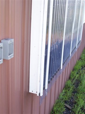 The collector is basically a 4 1/2” deep box built on the side of the hangar wall. The sheeting on the wall is steel. To keep it simple we would use the wall sheeting as our solar absorber. The side and bottom members to the box were slightly trimmed down 2 x 6’s, as 2 x 4’s would not have allowed enough depth on the box. Once the wall was boxed out to the appropriate size, we installed “stand offs”, strategically placed 2 x 4’s to hold the batten strips that we would eventually attach the glazing to. The spacing on the “stand-offs” was 24 “, providing us with supports horizontally every 2 feet. The batten strips, 1 x 3’s, were placed horizontally every 2’, providing support for the glazing on the same spacing.
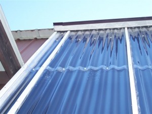 We used a wider board across the top of the collector to deal with the rain and snow coming off the roof. We installed flashing over the top board, running it up under the wall trim at the top of the wall. We did have a window to deal with, but designed the collector around it so we could maximize the size. We ended up at 11’ tall by 30’ long.
Once the collector box was framed up, it was time to paint everything flat black. Working outside this time of the year posed a problem, as the average high temps in mid December are 20 to 25 degrees. We had set up scaffolding to access all areas of the collector, so we attached boards to the top of the scaffolding. On paint day we would fashion a plastic sheeting enclosure from the roof to about 6’-8’ off the ground on the outside of the scaffolding. We used tarps to close off the bottom areas, and planned to fire up a salamander heater. We really didn’t like the fumes, but needed the heat to paint. We got lucky the day we planned to paint; the sun was shining. When we arrived about noon and closed up our enclosure to paint the collector, we were able to work in T-shirts under the plastic with the sun shining on the dark brown metal siding. The temp inside was a balmy 60+ degrees with outside temps in the mid 20’s. We were beginning to believe this solar stuff was going to work. We got everything painted flat black, and it dried before the sun quit warming the enclosure. We’re ready for glazing now.
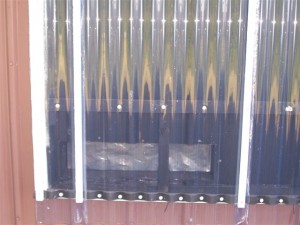
Holes were cut in the bottom outside corners through the wall for inlets from the hangar to the collector box. We trimmed the holes on the inside, installed screen to keep critters out, and installed a “flapper door” made out of 6-mil plastic to seal the collector from reverse flow during the night or on cloudy days.
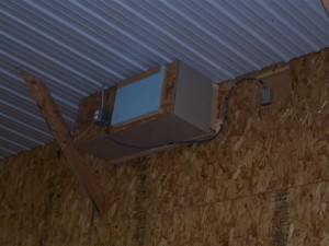
A hole was cut at the top to match up to the fan box we fashioned to enclose the fan motor. A friend in the HVAC business (Guy D. from D & L) provided us with a “free” 3-speed direct drive blower motor from a recently replaced furnace. The fan box was located as high as we could get it inside the building, and centered on the collector.
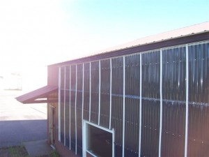 Using our plastic enclosure, the heater, and sunshine when we were lucky, we installed the corrugated polycarbonate. All the trim boards were pre-painted in the heated hangar, so other than the silicone sealant and our own comfort, the heat wasn’t quite so critical for working outside now. Once the collector box was closed up, the scaffolding and enclosure were torn down (we are into Christmas by now with snow), and we get to move into our heated hangar to finish this poorly timed project.
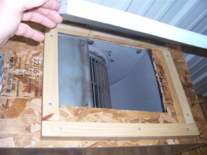 To avoid “reverse flow” on the collector, we wanted more than just the 6-mil plastic “damper doors” at the inlets. I cut some small pieces of pine board to trim out the outlet opening, cutting the trim boards so they placed the door at a slight angle off vertical. This would create a gravity effect on the Styrofoam door, ensuring it would close nicely without needing a mechanical closure system. The force of the fan will push the door open; gravity closes it when the fan shuts off.
To control the operation of the collector, we installed a “fan limit switch”. The sensor part of the switch protrudes into the box. It’s a variable temperature switch and I have it set to turn the fan on when the box hits 90 degrees. The collector is only put in the “active mode” during the late fall, winter, and early spring seasons. Up until this year, the ceiling fans were turned on during this time, and ran 24/7 for the entire heating season. During the last two years, Steve and I have been flying less, so the main heat to the hangar has been turned off. A feature Steve added this past year was to tie the ceiling fans to the solar collector fan circuit, so the ceiling fans do not run unless the collector is running.
We went live just after New Years Day. The results were pretty exciting. At the time, we were heating the hangar to 42 degrees; just enough to start the planes if we had an unexpected trip come up. The solar collector heated the hangar to 65 degrees. During the first couple weeks, I always seemed to have a reason to “run to the airport” when the sun had been shining for the day. The results were very consistent, with the 42’ x 64’ by 12’ ceiling building getting to 65 degrees when the collector was running. One day in late February I was snowmobiling with a friend when the high for the day barely hit 0 degrees. During lunch I told my friend “this isn’t fun when it’s this cold. Let’s go flying this afternoon”. We got to my hangar about 2 PM, on this miserably cold day, and the hangar temp was 60+ degrees.
The system cost us less than $500, and we realized a drop in our heat bill the first winter of about $200-$250. With a 2-3 year return, we’re pretty happy with the solar collector. While storing the heat to use later is not much of a cost effective option (water works much better for this), this is a pretty effective system that doesn’t cost a lot to build. Even with the heat turned off in our hangar, I know I can fly, without running to the airport and turning the heat on for half a day prior to launch, if the suns been shining.
