Jacobs 1800 Restoration
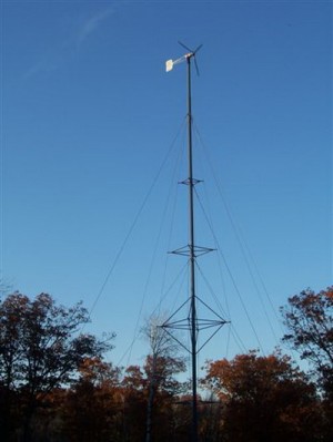 The 1930’s / 1940’s era Jacobs Wind Turbine restoration has been completed and the unit is up and making juice. Since the turbine makes DC power, it was more cost effective at this time to place the energy generated by this unit into low voltage heating elements in my solar tank. At least 9 months out of the year we can use the extra energy in the form of hot water, heating our DHW, hot tub and for supplemental home heating. This wind turbine will produce power in the lightest winds, converting wind energy to electricity that was not available from the previous turbine. It is also really quiet. I’ve gotten several comments from the neighbors how much they love this new turbine. At maximum speed and production, there is virtually no noise from the unit. I’ve finally developed a special ear to hear it in the dark, but for the first several days I could not tell if it was running after dark without looking at the power meter. Needless to say, we are very happy with the unit.
Click photos to enlarge;
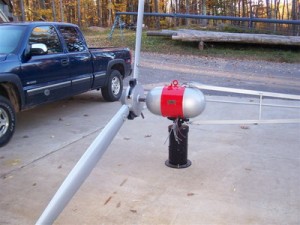
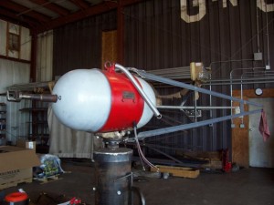
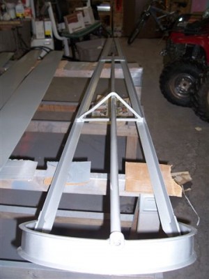
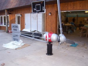 Completed restoration, assembled on the ground, and ready to be installed on the tower. All bolts and hardware, for the blades and the tail, are stainless steel.
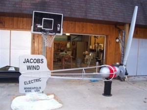
The other side of the restored unit. Note the tower in the lowered position in the background, next to the log pile.
The tail was restored to the exact lettering of the 1930’s-1940’s era turbines (which this is). Note the abbreviation for Minnesota at that time was MINN, not MN.
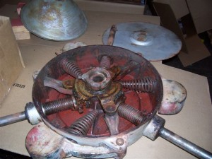
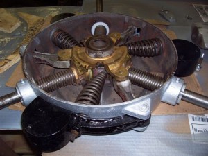
This is the variable pitch blade control designed by Mr. Jacobs. This control feature eliminates the need for a furling tail. The external flyweights overcome spring tension as the speed of the blades increase, twisting the blades to control over-speed and over generation of the turbine. Pretty impressive engineering for the 1930’s
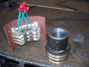
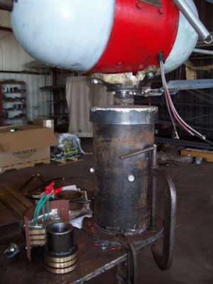
This is the slip ring made by my friend Larry. The actual generator motor is his; he rebuilt it years ago. The slip ring has since been installed immediately below the bearing assembly, enclosed by the same tube encasing the bearings.
A good picture of the generator on the recently completed bearing assy. We slightly modified the original mount bracket to fit to our bearing assy. Note the spring to “yaw” the tail out of the wind. Jacobs intentionally designed the tail to be straight to the turbine by tensioning the chain/cable assy, and the unit yaws the blades out of the wind when the cable is released. In the event of a broken cable/chain, the unit would yaw and protect itself. The circumstances that might require the need to manually yaw the turbine would be servicing the unit or a really significant weather event.
Close up of generator and bearing assy. Note the channel provided for the generator wiring to run down through the mount, and through the center of the bearing assy. The bottom flange on the bearing assy was made to fit the current top flange on my existing tower.
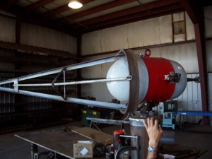
View of newly built tail framework, showing the tail in a partially yawed position. You can see the pulley for the chain/cable bolted to the generator. The chain/cable comes through a small access hole in the mount, through the pulley, and attaches to the loop in the tail structure “swing arm”. There are physical stops for the tail in both the locked and furled positions.
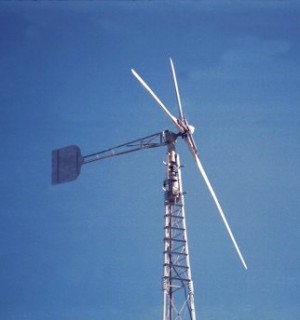
A working Jacobs on a tower. This is a later model though, as you can see the external springs on the blades. This design used springs for pitch function on the blades.
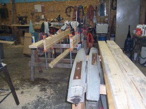
A picture of the old blades at the right front, and the new blade blanks being laminated, to the left and rear, on the saw horses.
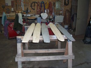
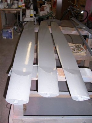
3 Finished blades, with a couple old damaged blades. The profiles of the old blades were mapped on both sides, and replicated to the new blades.
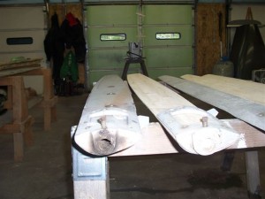
End view of new and old blade showing twist on flat side of blade.
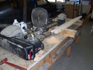
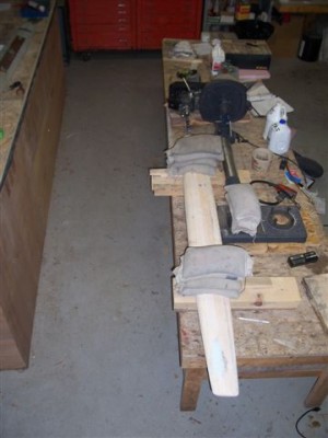
I took my drill press base off, put the press on a low work bench, leveled and squared it to the bench. Since I have about fifty 25 lb. shot bags for my airplane work, I laid 100 lbs on the press to keep it from moving (it was pretty stable already). Then I took an original blade out that was “mapped” for building the new blades, and verified I was straight to the drill press with multiple measurements. I installed blocking and wedges to support the blade to the exact location required to properly drill the new blades.
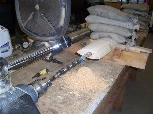
Once everything was aligned, I secured the blades with 200 lbs of shot bags and started drilling. I could only get just under 4″ on the drill press for depth, so the process of aligning the press to the blades was repeated about 4 times (I pilot drilled to avoid drift with the big bit). I imagine this drill process was streamlined at the Jacobs factory to be a lot faster than this.
A view of the end while drilling the mount holes. The drill bit is one left over from a log home building project about 25 years ago.
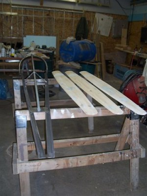
Blades & Tail frame ready for two part epoxy primer and paint
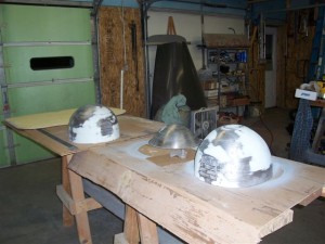
Front and back generator cones finished with the bodywork and ready for primer & paint.
Painted tail frame. Notice round tube’s been straightened and re-welded to center truss since it’s was last on the turbine motor (I know, I’m a bit anal)
Blades after final paint
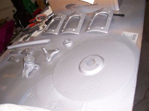
Hardware painted
Completely rebuilt variable pitch hub for blade mounting and blade pitch control. The bearings for this were “special order” (for me anyway) and were not cheap.
*****
My 5.5kw Breezy Wind Turbine
A great project description is on my friend Gary Reysa’s site;
www.builditsolar.com/Projects/Wind/TomTurbine/Main.htm
Update 8/30/10
With continued dissatisfaction of this unit, I have removed the turbine from the tower. Production, or lack of, is the main reason. Some other compelling factors are the noises it makes both in and out of production. The blades are noisy in the wind, probably due to the intentionally designed poor efficiency blade for high speed wind protection. The other noise is the “clang” I get every time it locks in. In any winds besides a gale, the unit is constantly locking in and out, sometime as often as 6-8 times a minute. My neighbors have been pretty accommodating, but given the poor production on top of the noise, I felt it best to look at other turbine options.
In fairness to the designers, I must note a couple things.
- I’ve talked with builders in good wind zones, and this unit WILL make good power. A builder in Saskatchewan, CA inquired about my tower while building his second Breezy, a 10KW unit. His 5.5 KW unit was making $80 worth the juice a month (two years ago). I’m in a poor wind zone, and shame on me for not being more diligent in understanding the weakness of this turbine in lower wind zones, and my lack of “regular” quality winds.
- I consulted older wind zone maps 3-4 years ago when in the research stage of doing this project. These maps put me in a borderline between a 2 & 3 wind zone. I think this unit will perform in a zone 3 or higher to your expectations. Newer wind maps now depict me bordering between a 1 & 2 wind zone for my location.
- A unique trait of this turbine, unlike most conventional turbines, is the minimum threshold of wind required for it to generate electricity. It takes 2200 watts of wind resource to start this unit, and going from free spinning of the blades to supporting 2200 watts requires significant wind. Alternatively, most wind generators will start with a much lower wind generation point, and my wind resource would support 1,000 watts, all day, for days at a time. Unfortunately, there are no reasonably priced alternatives when looking for a grid tie A/C generator.
I’m presently restoring an old Jacobs 1800 watt DC unit, and will likely just punch the energy into heating elements in my solar tank. I’ll explore grid tie options later, but suspect, from research so far, this will be cost prohibitive. At least for now, I’ll be able to watch a wind turbine make power in almost any wind, and the energy will be converted to heat for my DHW, Hot Tub, and home heating during 7 months of the year.
